Before making any changes to the standard setup, make sure you can get around the track without crashing. Changes to your vehicle will not be beneficial if you can't stay on the track. Your goal is consistent laps.
Once you can get around the track consistently, start tuning your vehicle. Make only ONE adjustment at a time, testing it before making another change. If the result of your adjustment is a faster lap, mark the change on the included setup sheet (make adddtional copies of the sheet before writing on it). If your adjustment results in a slower lap, revert back to the previous setup and try another change.
When you are satisfied with your performance, fill in the setup sheet thoroughly and file it away. Use this as a guide for future track days or conditions.
Periodically check all moving suspension parts. Suspension components must be kept clean and move freely without binding to prevent poor and/or inconsistent handling.
Proper motor gearing will result in maximum performance and run time while reducing the chance of overheating and premature motor failure. The gear ratio chart lists recommended starting gear ratios for the most widely used motor types. Gear ratios will vary depending upon motor brand, wind, and electronic speed control. Consult your motor and electronic speed control manufacturers for more information. Team Associated is not responsible for motor damage due to improper gearing.
Rows marked * are gearings are for use with advanced timing speed control settings!
Due to the original design of the RC10, motors exceeding the power of a 8.5T motor are NOT recommended, to prevent damage to the drivetrain!
RC10 Classic Gear Ratio Chart (Internal Gear Ratio 2.60:1)
| Motor | Pinion | Spur | FDR |
| 27T Stock Brushed | 18 | 81 | 8.23:1 |
| 19T Super Stock Brushed | 18 | 81 | 8.23:1 |
| 17.5 Reedy Sonic Brushless * | 19 | 81 | 7.80:1 |
| 17.5 Reedy Sonic Brushless | 27 | 81 | 5.49:1 |
| 13.5 Reedy Sonic Brushless * | 18 | 81 | 8.23:1 |
| 13.5 Reedy Sonic Brushless | 26 | 81 | 5.70:1 |
| 10.5 Reedy Sonic Brushless | 19 | 81 | 7.80:1 |
| 9.5 Reedy Sonic Brushless | 18 | 81 | 8.23:1 |
| 8.5 Reedy Sonic Brushless | 18 | 81 | 8.23:1 |
Rows marked * are gearings are for use with advanced timing speed control settings.
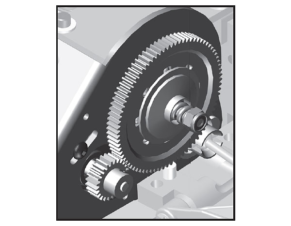
You should be able to rock the spur gear back and forth in the teeth of the pinion gear without making the pinion gear move. If the spur gear mesh is tight, then loosen the #31531 screws and move the motor away, then try again. A gear mesh that is too tight or too loose will reduce power and damage the gear teeth.
Be sure to only use Associated diff lube #6636, and apply a small amount on both sides of the diff balls. Do not use this diff grease anywhere else on the vehicle! It is not intended as a lubricant (Use only Associated diff lube as it has special additives to ensure the balls roll instead of slide).
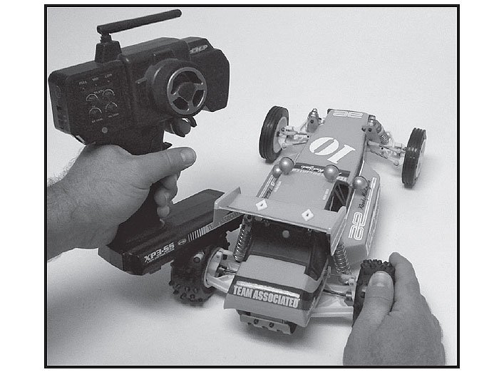
The RC10 Classic is not equipped with a slipper clutch like most current RC vehicles are. Therefore, particular care and attention is necessary when setting the VariLok differential. Set the differential by starting with the 5-40 nut flush with the end of the diff shaft. Next, turn on the car and hold the tires (as seen below) with transmitter in hand. Quickly give the car a 75-100% burst of throttle. Note, if the spur gear spins and the car does not move forward then the diff is too loose. Adjust the diff nut in 1/8-turn increments until the spur gear doesn't slip. At this point, the diff is set as free as possible without slipping. Tightening the diff nut even further will increase the amount of power that is transferred to the tire that has the most load and will not 'diff out' as easily. Locking down the diff nut is not recommended because the only slipping that can occur
will be between the drive rings and hubs. This can create a tremendous amount of heat.
The wheelbase on the RC10 Classic can be adjusted by moving the rear arm mounts forward or backwards. The kit setting has the arm mount back, which provides the most stability over bumps and rhythm sections. Going to the shorter wheelbase option will improve rear traction.
Changing the length of the camber link is considered a bigger step than adjusting the ball end height on the tower. Shortening the camber link (or lowering the ball end) will give the front end less roll and quicken steering response. Lengthening the camber link (or raising the ball end) will give the front more roll and slower steering response. Longer camber links are typically used on high grip tracks and shorter links tend to work better on medium-grip loose tracks.
Raise or lower the ball end on the front shock tower
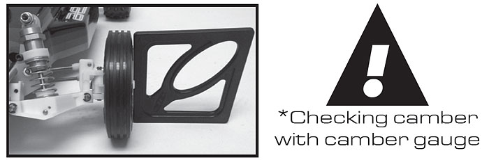
Camber describes the angle at which the tire and wheel rides when looked at from the front. Negative camber means that the tire leans inward at the top. A good starting camber setting is -1°. Use the included #1719 camber gauge to set your camber. Positive camber, where the top of the tire is leaning out, is not recommended.
Caster describes the angle of the kingpin as it leans toward the rear of the vehicle. Positive caster means the kingpin leans rearward at the top. The supplied 15° caster blocks (#6213) are recommended in most cases. For less corner-entry steering and more exit steering, try the optional 30° caster blocks (#6210). Optional 30° caster blocks may require trimming of the stock front arms for clearance.
Changing the length of the camber link is considered a bigger step than adjusting the ball end height on the rear chassis brace. Shortening the camber link (or lowering the ball end) will give the rear end less roll and the car will tend to accelerate or "square up" better. Lengthening the camber link (or raising the ball end) will give the rear more roll and more cornering grip. Longer camber links are typically used on high grip tracks, while shorter links tend to work better on medium grip loose tracks. The far inside hole was a tuning option introduced later on. It requires a 1.65" turnbuckle (#6262, 1403, or 6256).
Raise or lower the ball end by adjusting the ballstud location on the bulkhead
Camber describes the angle at which the tire and wheel rides when looked at from the back. Negative camber means that the tire leans inward at the top. A good starting camber setting is -1°. Use the included #1719 camber gauge to set your camber. Adding a small amount of positive camber, where the top of the tire is leaning out, will tend to improve straight-line acceleration on loose tracks.
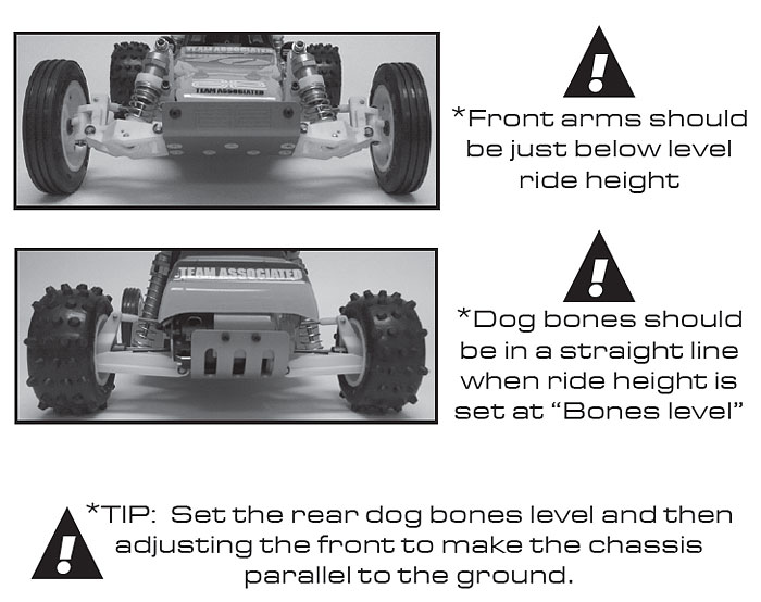
Ride height is the distance from the ground to the bottom of the chassis. The standard front ride height setting is with the front arms just below level or 24mm (use a Ride Height Gauge #1449 to measure ride height setting). Check the ride height by lifting up the entire car about 8-12 inches off the bench and drop it. After the suspension "settles" into place, measure ride height (Ride Height Gauge #1449). Raise or lower the shock collars as necessary so that the left and right arms appear to be level.
The rear ride height setting you should use most often is with the outdrive, driveshaft, and axles all on the same imaginary horizontal line (referred to as "bones level") or 24mm (use a Ride Height Gauge #1449 to measure ride height setting). Check the ride height by lifting up the entire car about 8-12 inches off the bench and drop it. After the suspension "settles" into place, measure ride height (Ride Height Gauge #1449). Raise or lower the shock collars as necessary so that the left and right driveshafts appear to be level.
Brushed motors require frequent maintenance to keep performance levels at their maximum. Between runs and after letting the motor cool completely, inspect the brushes to ensure that they are moving freely in their holders.
Remove the springs and slide the brushes in and out of their holders, checking for any resistance or rough spots. If found, remove the brush and carefully wipe it clean. Removing buildup will allow the brush to slide freely and create maximum contact with the commutator, resulting in maximum power output.
After every 3-5 runs, remove the brushes from their holders and inspect the tips for wear or burning. If there is noticeable wear (less than 75% of the brush remaining), it is best to cut the commutator and replace the brushes with a new pair. If the tips become a burned blue color, the lubricant in the brush has been burned away and new brushes should be installed.
Occasionally, the motor should be cleaned with a soft brush to prevent dirt buildup around the brush hood area and ball bearings. At this time, it is a good idea to add one drop of bushing / bearing oil to each bushing or ball bearing.
If using a brushless motor, please refer to the motor manufacturer's guidelines for proper maintenance.
