Instruction Manual
-
1. Introduction, p2
Thank you for purchasing this Team Associated product. This assembly manual contains instructions and tips for building and maintaining your new vehicle. Please take a moment to read through the manual and familiarize yourself with the steps. We are continually changing and improving our designs; therefore, actual parts may appear slightly different than the illustrations. New parts will be noted on supplementary sheets located in the appropriate parts bags. Check each bag for these sheets before you start to build.
-
2. RC10B6D KIT Features, p2
- 3-gear stand-up Stealth™ transmission with lightweight aluminum top shaft
- Ball differential with 14 carbide balls for smooth operation and maximum traction
- Carbon-fiber shock towers and flat front arms with three shock mounting positions
- Reverse bell-crank steering rack design allows more room for electronics
- Hard-anodized aluminum pocketed chassis with optional weights available for optimal weight bias
- V2 12mm Big Bore threaded aluminum shocks with 3mm TiN coated shafts and low-friction x-rings for improved smoothness
- One-piece steering blocks with bolt-on Ackermann plates
- Adjustable battery hold-down strap allows weight bias tuning
- Lightweight and durable aluminum C plate and aluminum ballstud mount
- Repositioned A plate provides maximum front-end clearance
- Centralized motor positioning for optimum side-to-side balance
- Updated ball cups and turnbuckles for precise adjustments and durability
- Factory Team Aluminum Shock Bushings provide stable shock mounts
- Team Associated clear body and screw-mounted wing by JConcepts™
- Factory Team upgraded ball bearings
-
3. Tools Needed, p2
Your new B6 Team Kit comes unassembled and requires the following items for completion (refer to catalog section for suggestions):
Online Item Radio RC two-channel surface frequency radio system Batteries AA-size batteries for transmitter (#302 alkaline) ESC Electronic Speed Control, ESC (#27002) Servos Steering servo (#27106, #27107) Motors RC electric motor Pinions Pinion gear (48P), size determined by type/wind of motor Chargers Battery charger (a peak detection charger, or LiPo compatible charger) Batteries 2 cell LiPo battery pack (#310, 317, 737, 738) Fluids Cyanoacrylate glue (#1597) Fluids Thread locking compound (#1596) Wheels Wheels with 12mm Hex:
Front Wheels #9690, #9691, #91572, #91573
Rear Wheels #9695, #9696, #91570, #91571Tires and Inserts, Fronts and Rears Polycarbonate specific spray paint Tools Included
topOnline Item Tools Allen wrenches 1.5mm, 2.0mm Tools #1113 12mm Shock Tool Multi-wrench Other Helpful Items
Online Item Fluids Silicone Shock Fluid Tools Body Scissors (AE Part # 1737) Tools Shock Shaft Pliers (#1675) Tools FT Hex and Nut Wrenches (AE Part #1519) Fluids Green Slime shock lube (AE Part # 1105) Reamer / Hole Punch Wire Cutters Needle Nose Pliers Hobby Knife Soldering Iron Calipers or a Precision Ruler -
4. Symbols Used, p4
 This symbol indicates a special note or instruction in the manual.
 This symbol indicates a Racer's Tip.
 The following is not included with this app. There is a 1:1 hardware foldout page in the front of the [printed] manual. To check the size of a part, line up your hardware with the correct drawing until you find the exact size. Each part in the foldout has a number assigned to it for ordering replacement parts.
 -
5. Bag 1, Steering Rack
 top
Show/Hide Parts
top
Show/Hide Parts
Online Name 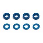
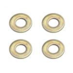
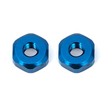
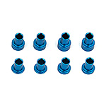
#31286 Ballstud Washers, aluminum 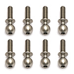
#91048 Heavy-duty Ballstuds, 8 mm 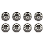
#91475 Bearings, 3x7x3 mm 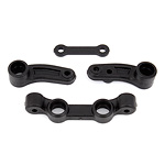
#91667 B6 Steering Assembly  top
Show/Hide Parts
top
Show/Hide Parts
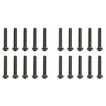
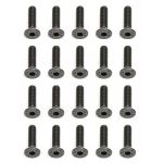
#25188 Screws, 3x20 mm BHSS 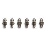
#31283 Ballstuds, long, 5 mm 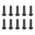
#89202 Screws, 3x12 mm BHCS #91667 B6 Steering Assembly  Show/Hide Parts
#31286 Ballstud Washers, aluminum 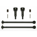
#91046 4x4 Rear CVA Kit 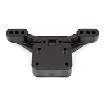
#91655 B6 Front Ballstud Mount -
6a. Bags 2-4, Bulkhead, rails, servo
Bags 2-4 step 1

There are two bulkhead settings (25° and 30°). 25° is the standard setting. The arrow should point forward for the desired setting: top
Show/Hide Parts
top
Show/Hide Parts
Online Name 
#25204 Screws, 3x16 mm FHCS 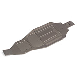
#91650 B6 Chassis 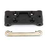
#91656 B6 Bulkhead Bags 2-4 step 2
 Show/Hide Parts
#25201 Screws, 3x8 mm FHCS 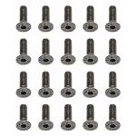
#25202 Screws, 3x10 mm FHCS 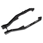
#91652 B6 Side Rails 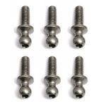
#31284 Ballstuds, long, 8 mm  top
Show/Hide Parts
top
Show/Hide Parts
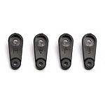
#9180 Servo Horns, molded #31284 Ballstuds, long, 8 mm #31286 Ballstud Washers, aluminum 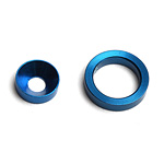
#89009 Servo Support Ring & Washer Bags 2-4 step 3

 Show/Hide Parts
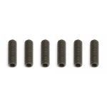
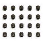
#4671 Set Screws, 3x0.5x10 mm #31286 Ballstud Washers, aluminum 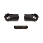
#91724 B6 Steering Link  top
Show/Hide Parts
top
Show/Hide Parts
#7337 Washers, .250 x .125 x .015 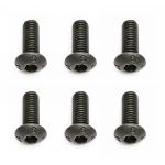
#31532 Screws, 3x0.5x8 mm BHCS 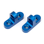
#91719 B6 Servo Mounts Bags 2-4 step 4

Parts
#25211 Screws, 3x10 mm BHCS -
6b. Bags 2-4, Top plate, arms
Bags 2-4 step 5

Parts
#89202 Screws, 3x12 mm BHCS
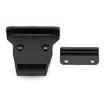
The front hinge pin brace has a sharp-edged side and a rounded-edged side. Mount the sharp-edged side towards the bulkhead:
Bags 2-4 step 6
 top
Show/Hide Parts
top
Show/Hide Parts
Online Name 
#31510 Screws, 2x0.4x4 mm BHCS #91656 B6 Bulkhead (and front hinge pin brace) 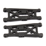
#91671 B6 Flat Front Arms -
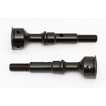
7. Bags 5-8, Steering block, caster block
Bags 5-8 step 1
 top
Show/Hide Parts
top
Show/Hide Parts
Online Name 
#31531 Screws, 3x0.5x6 mm BHCS 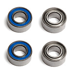
#91560 T Bearings, 5x10x4 mm 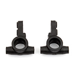
#91677 B6 Steering Blocks 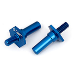
#91682 B6 Front Axles  Show/Hide Parts
#31286 Ballstud Washers, aluminum #91048 Heavy-duty Ballstuds, 8 mm 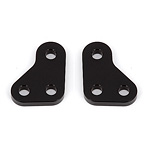
#91679 B6 Steering Block Arms #91682 B6 Front Axles  Show/Hide Parts
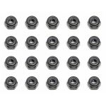
#25215 Locknuts, M3 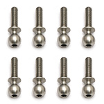
#91049 Heavy-duty Ballstuds, 10mm 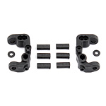
#91675 B6 Caster Blocks and Inserts -
8. Bags 9-10, Arm mounts
Bags 9-10 step 1
 top
Show/Hide Parts
top
Show/Hide Parts
Online Name #25201 Screws, 3x8 mm FHCS 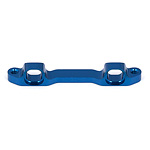
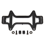
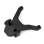
#91686 B6 Aluminum Arm Mount, C 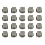
#92014 Arm Mount Inserts 
The arm mount insert chart shows the different adjustments possible. 3° toe/1° anti-squat is the kit setup. NOTE: Shown below is the orientation of the inserts when installing them into arm mount C. If the inserts are not matched correctly from left to right, suspension binding can occur.
Bags 9-10 step 2
 Show/Hide Parts
Online Name 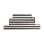
#91670 B6 Hinge Pin Set 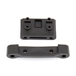
#91692 B6 Rear Gearbox Brace 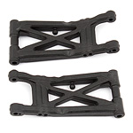
#91695 B6 Rear Arms -
9a. Bags 11-14, Ball diff, outdrives
Bags 11-14 step 2
 Show/Hide Parts
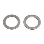
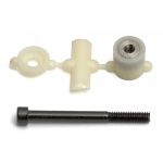
#6573 Diff Thrust Washer and Bolt 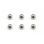
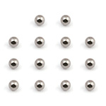
#6574 Diff Thrust Balls, 5/64 in As you tighten the diff bolt, you will notice the T-nut ears moving closer to the bottom of the outdrive slot. This compresses the spring behind the T-nut. The spring should be completely compressed at the time the T-nut reaches the end of the slot.
Caution! Pay close attention to the feeling when the spring is completely compressed. Do not overtighten the bolt. When you feel the spring completely compressed, loosen the diff bolt 1/8" of a turn. Your diff should now operate smoothly but with resistance as the outdrives move in opposite directions. After you have driven the car once, re-check the diff setting.
-
9b. Bags 11-14, Gearbox
Bags 11-14 step 4
 Show/Hide Parts
Online Name #91560 FT Bearings, 5x10x4 mm 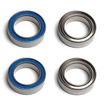
#91563 FT Bearings, 10x15x4 mm 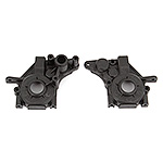
#91706 B6 Standup Gearbox, 3-gear  top
Show/Hide Parts
top
Show/Hide Parts
Online Name 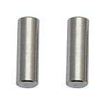
#91132 4x4 FT Idler Shafts, aluminum #91560 FT Bearings, 5x10x4 mm 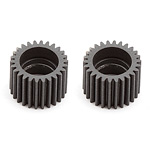
#91717 B6 Idler Gear, 26T, standup Bags 11-14 step 5

Parts
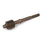
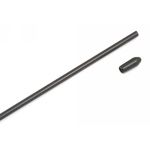
#91710 B6 Top Shaft  top
Show/Hide Parts
top
Show/Hide Parts
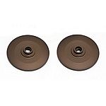
#7485 FT V2 Slipper Hubs 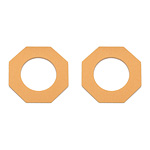
#9603 Slipper Pads 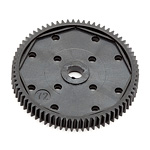
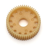
#9649 Spur Gear, 72T 48P 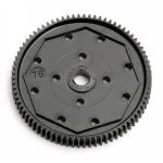
#9652 Spur Gear, 78T 48P  The assembly instructions give you a base setting for your clutch. Turn the nut on the shaft so that the end of the top shaft is even with the outside of the nut. At the track, tighten or loosen the nut in 1/8 turn increments until you hear a faint slipping sound for 1-2 feet on takeoffs.
Another popular way to set the clutch is to hold both rear tires firmly in place (hand on one tire and radio pushing down on other tire) and apply short bursts of throttle. If the clutch is properly set, the front tires should lift slightly up off the surface.Bags 11-14 step 8
 top
Show/Hide Parts
top
Show/Hide Parts
Online Name 
#25187 Screws, 3x14 mm BHCS #91048 Heavy-duty Ballstuds, 8 mm #31286 Ballstud Washers, aluminum 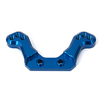
#91693 B6 Rear Ballstud Mount -
10. Bags 15-16, Rear hub, axles
Bags 15-16 step 1


(Understanding the chart: Drawing shows #91697 insert at 0/3up. When installed on the arm, it will lower the axle height to 0-low level. In that configuration, ballstud location of B-up is recommended.)
top Show/Hide PartsOnline Name #25215 Locknuts, M3 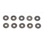
#89218 Washers, 3x8 mm #91049 Heavy-duty Ballstuds, 10mm 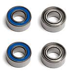
#91562 FT Bearings, 6x13x5 mm #91563 FT Bearings, 10x15x4 mm 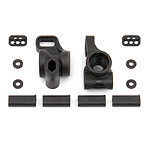
#91697 B6 Rear Hubs 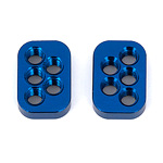
#91698 B6 Rear Hub Link Nuts Bags 15-16 step 2
 Show/Hide Parts
#71019 Heavy Duty CVA Axles 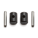
#91438 CVA Rebuild Kit 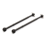
#91439 CVA Bones  top
Show/Hide Parts
top
Show/Hide Parts
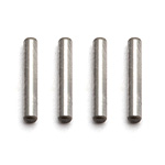
#91436 CVA/Wheel Hex Pins 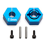
#91610 Clamping Wheel Hexes, 7.0mm 
#91611 Screws, 1.6x5 mm SHCS 
Parts
#91697 B6 Rear Hubs -
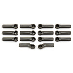
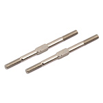
11. Bag 17, Turnbuckles, ball cups


-
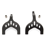
12. Bags 18-19, Towers, wing mounts
Bags 18-19 step 1
 top
Show/Hide Parts
top
Show/Hide Parts
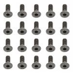
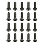
Online Name #25188 Screws, 3x20 mm BHSS 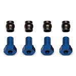
#91533 Shock Bushings, short 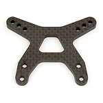
#91661 B6 Front Shock Tower, flat 
Parts
#25203 Screws, 3x12 mm FHCS Bags 18-19 step 2
 top
Show/Hide Parts
top
Show/Hide Parts
Online Name #89202 Screws, 3x12 mm BHCS 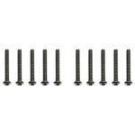
#89204 Screws, 3x24 mm BHCS 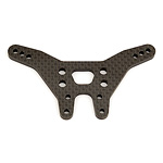
#91665 B6 Rear Shock Tower 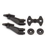
#91718 B6 Wing/Body Mount 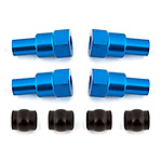
#91720 B6 Shock Bushings, long 
Parts
#89202 Screws, 3x12 mm BHCS -
13. Bags 20-22, Shocks
Bags 20-22 step 1
 top
Show/Hide Parts
top
Show/Hide Parts
Online Name 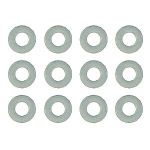
#4187 Nylon Spacers, 1/32 in. (.030 in) #31510 Screws, 2x0.4x4 mm BHCS 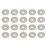
#89278 Washers, 2.5 mm 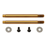
#91615 3x21 mm Shock Shafts (V2), TiN 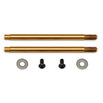
#91619 3x27.5 mm Shock Shafts (V2), TiN 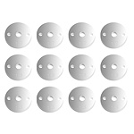
#91634 12mm Shock Pistons, V2 Bags 20-22 step 2
 top
Show/Hide Parts
top
Show/Hide Parts
Online Name 
#1105 FT Green Slime Shock Lube 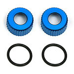
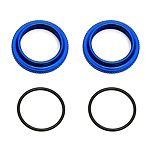
#31327 VCS3 Shock Bottom Caps 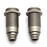
#91480 12x23 mm V2 Shock Bodies 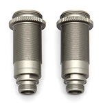
#91481 12.27.5 V2 Shock Bodies 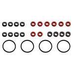
#91491 12 mm V2 Shock Rebuild 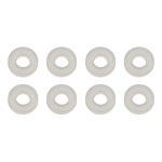
#91493 Factory Team Low Friction X-Rings 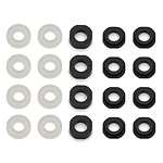
#91495 12 mm V2 X-Ring Rebuild Kit
There is a short and long shock eyelet. Front shocks use the long eyelet, rear shocks use the short eyelet. (Note that the #91721 pivot balls are silver metal. They are to be distinguished from a similar part that is black plastic -- the #91447 shock bushing.) top
Show/Hide Parts
top
Show/Hide Parts
#1105 FT Green Slime Shock Lube 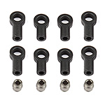
#91721 B6 Shock Eyelets Bags 20-22 step 3

Shock Bleeding Steps:
Show/Hide Parts
1. Before assembly, get each bleed screw and thread it 1-2 turns into the #91449 shock cap, then remove the screw. This will make it easier when you are bleeding your shocks.
2. Pull shock shaft down.
3. Fill shock body 3/4 full with silicone shock fluid.
4. Slowly move the shock shaft up and down to remove air from under the piston.
5. Wait for bubbles to come to surface.
6. Fill shock body to top with silicone shock fluid.
7. Place a drop of oil in the cap and on cap threads.
8. Install cap (without bleed screw) and tighten completely.
9. Slowly compress shaft all the way to bleed excess silicone shock fluid out the hole in the cap (use rag around shock to catch excess fluid).
10. Install M2x4mm button head screw until snug while shaft is fully compressed.Online Name 
#5422 Silicone Shock Fluid, 30wt 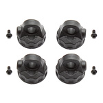
#91449 12MM V2 Composite Shock Cap with O-ring and bleeder screw 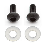
#91492 12 mm V2 Bleeder Gaskets  top
Show/Hide Parts
top
Show/Hide Parts
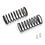
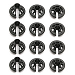
#91328 12mm Front Springs, white, 3.30 lb 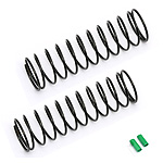
#91336 12mm Rear Springs, green, 2.00 lb Bags 20-22 step 5

(The #91447 Shock Bushings are black plastic.)
top Show/Hide PartsOnline Name #25188 Screws, 3x20 mm BHSS 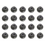
#25612 Locknuts, M3 with flange 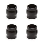
#91447 Shock Bushing Balls  top
Show/Hide Parts
top
Show/Hide Parts
#25187 Screws, 3x14 mm BHCS #25612 Locknuts, M3 with flange #91447 Shock Bushing Balls -
14. Bag 23, Motor mounting
Bag 23 step 2

Set The Gear Mesh:
You should be able to rock the spur gear back and forth in the teeth of the pinion gear without making the pinion gear move. If the spur gear mesh is tight, then loosen the #31532 screws and move the motor away, then try again.
A gear mesh that is too tight or too loose will reduce power and damage the gear teeth. top
Show/Hide Parts
top
Show/Hide Parts
#31531 Screws, 3x0.5x6 mm BHCS 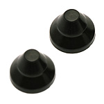
#91089 4x4 Belt Cover Cap 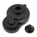
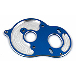
#91712 B6 Gear Cover, 3-gear -
15a. Bags 24-26, Electronics
Bags 24-26 step 1

Parts
#6727 Servo Tape Bags 24-26 step 2

Parts
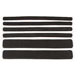
#91734 B6 Battery Foams Bags 24-26 step 3


Parts
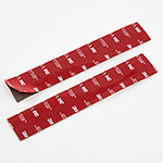
#91731 B6 Battery Strap Bags 24-26 step 4
 top
Show/Hide Parts
top
Show/Hide Parts
Online Name #25211 Screws, 3x10 mm BHCS #89218 Washers, 3x8 mm #91731 B6 Battery Strap 
Parts
#91729 B6 Thumbscrews -
15b. Bags 24-26, Wing, body, wheels
Bags 24-26 step 5
 top
Show/Hide Parts
top
Show/Hide Parts
Online Name #25203 Screws, 3x12 mm FHCS #91718 B6 Wing/Body Mount 
#91741 B6 Wing  top
top
There are three body trimming options depending on what transmission and shock position you choose to run:
Cut Line A: Laydown transmission + shocks mounted at rear of arm.
Cut Line B: Laydown transmission + shocks mounted in front of arm.
Cut Line C: 3-Gear standup transmission.Bags 24-26 step 7

Parts
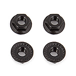
#91738 Nuts, M4 Serrated Nuts


Tuning Tips
-
Tips for Painting
Your B6 Team Kit comes with a clear polycarbonate body. You will need to prep the body before you can paint it.
top
Wash the INSIDE thoroughly with warm water and liquid detergent (do not use any detergents with scents or added hand lotion ingredients!). Dry the body using a clean, soft, lint-free cloth. Use the supplied window masks to cover the windows on the INSIDE of the body (RC cars get painted on the inside). Using high quality masking tape, apply tape to the inside of the body to create a design. Spray the paint (using either rattle can or airbrush) on the inside of the body (preferably dark colors first, lighter colors last).
NOTE: Use ONLY paint that is recommended for use with polycarbonate plastics. If you do not, you can destroy the plastic body!
After the paint has completely dried (usually after 24 hours), cut the body along the trim lines. Make sure to drill or use a body reamer to make the holes for the antenna if needed! Use hook and loop tape to secure the body to the side rails of the vehicle. -
Tips for Beginners
Tips for Beginners
Before making any changes to the standard setup, make sure you can get around the track without crashing.
top
Changes to your vehicle will not be beneficial if you can't stay on the track. Your goal is consistent laps.
Once you can get around the track consistently, start tuning your vehicle. Make only ONE adjustment at a time, testing it before making another change. If the result of your adjustment is a faster lap, mark the change on the included setup sheet (make additional copies of the sheet before writing on it). If your adjustment results in a slower lap, revert back to the previous setup and try another change.
When you are satisfied with your vehicle's performance, fill in the setup sheet thoroughly and file it away. Use this as a guide for future track days or conditions. Periodically check all moving suspension parts. Suspension components must be kept clean and move freely without binding to prevent poor and/or inconsistent handling. -
Gear Box Type
Gear Box Type


Selecting the correct gearbox depends on the type of track it will be used on. The optional 4-gear standup gear box is for the lowest grip conditions. This gearbox moves the weight towards the rear of the car and also uses the rotation of the motor to transfer weight to the rear while on-power. The 3-gear standup gearbox also moves the weight towards the rear of the car, but in this configuration, the motor's rotation helps with on-power steering.
top
The laydown gearbox is used on high-grip conditions when on-power steering and stability are most important. This gearbox will change directions the quickest and generate the most steering. -
Motor Gearing
Motor Gearing
Proper motor gearing will result in maximum performance and run time while reducing the chance of overheating and premature motor failure. The gear ratio chart lists recommended starting gear ratios for the most widely used motor types. Gear ratios will vary depending upon motor brand, wind, and electronic speed control. Consult your motor and electronic speed control manufacturers for more information.
Team Associated is not responsible for motor damage due to improper gearing.
B6 Gear Ratio Chart (Internal Gear Ratio: 2.60:1)
topMotor Pinion Spur Final Drive Ratio 17.5 Reedy Sonic Brushless 31 69 5.79:1 13.5 Reedy Sonic Brushless 30 75 6.50:1 10.5 Reedy Sonic Brushless 24 78 8.45:1 9.5 Reedy Sonic Brushless 23 78 8.82:1 8.5 Reedy Sonic Brushless 22 78 9.22:1 7.5 Reedy Sonic Brushless 21 78 9.65:1 6.5 Reedy Sonic Brushless 20 78 10.14:1 3300kV Brushless 21 81 10.03:1 3900kV Brushless 21 81 10.03:1 4900kV Brushless 19 81 11.08:1 6100kV Brushless 18 81 11.70:1 -
Set the Gear Mesh
Set the Gear Mesh

You should be able to rock the spur gear back and forth in the teeth of the pinion gear without making the pinion gear move. If the spur gear mesh is tight, then loosen the #31532 screws and move the motor away, then try again.
top
A gear mesh that is too tight or too loose will reduce power and damage the gear teeth. -
Slipper Clutch
Slipper Clutch
The assembly instructions give you a base setting for your clutch. Turn the nut on the shaft so that the end of the top shaft is even with the outside of the nut. At the track, tighten or loosen the nut in 1/8-turn increments until you hear a faint slipping sound for 1-2 feet on takeoffs. Another popular way to set the clutch is to hold both rear tires firmly in place and apply short bursts of throttle. If the clutch is properly set, the front tires should lift slightly up off the surface.
top -
Caster
Caster
Caster describes the angle of the caster block as it leans toward the rear of the vehicle. Positive caster means the kingpin leans rearward at the top.
top
The B6 includes three inserts to adjust caster angle at the caster block: 0°, 2.5°, and +5°. The total caster angle is the sum of the kick-up angle and the caster block angle. Standard total caster angle for the B6 is 30°, with 25° kick-up and +5° caster block angle.
For less entry steering and more exit steering, try 0° caster block angle. -
Front Camber
Front Camber

Camber describes the angle at which the tire and wheel ride when looked at from the front. Negative camber means that the tire leans inward at the top.
top
A good starting camber setting is -1°. Positive camber, where the top of the tire is leaning out, is not recommended.
Optional #1719 camber gauge can be used to set camber. -
Rear Camber
Rear Camber
Camber describes the angle at which the tire and wheel ride when looked at from the back. Negative camber means that the tire leans inward at the top.
top
A good starting camber setting is -1°. Adding a small amount of positive camber, where the top of the tire is leaning out, will tend to improve straight-line acceleration on loose tracks.
Optional #1719 camber gauge can be used to set camber. -
Front Camber Links
Front Camber Links

Changing the length of the camber link is considered a bigger step than adjusting the ball end height on the tower.
top
Shortening the camber link (or lowering the ball end) will give the front end less roll and quicken steering response.
Lengthening the camber link (or raising the ball end) will give the front more roll and slower steering response. Longer camber links are typically used on high-grip tracks and shorter links tend to work better on medium-grip loose tracks. -
Rear Camber Links
Rear Camber Links

Changing the length of the camber link is considered a bigger step than adjusting the ball end height on the rear chassis brace.
top
Shortening the camber link (or lowering the ball end) will give the rear end less roll and the car will tend to accelerate or "square up" better.
Lengthening the camber link (or raising the ball end) will give the rear more roll and more cornering grip. Longer camber links are typically used on high-grip tracks, while shorter links tend to work better on medium-grip loose tracks.
The kit setting is the best compromise of cornering grip and acceleration. -
Ackermann
Ackermann

Ackermann is the angle difference between the front wheels when they are turned to steer the car. For minimal tire slip, it is standard for the inside wheel to steer to a greater angle than the outside wheel.
top
The B6 allows Ackermann adjustments by changing the washer thickness used behind the steering rack ballstuds. The kit setup uses 2mm washers and is most common for racing conditions. If corner entry steering is too aggressive, try increasing the Ackermann by removing shims from behind the steering rack ballstuds. Increasing the Ackermann will increase the angle difference of the front wheels when steered, resulting in a more stable car on corner entry. -
Kickup
Kickup
Kickup is the angle the front suspension arm mounts at where the front of the arm is higher than the rear.
top
The standard kickup angle for the B6 is 25°, and is most common. If more corner entry steering is desired, try the included 30° front bulkhead. -
Axle Height
Axle Height

Axle height is used to keep roll centers similar when large ride height changes are made. As a rule of thumb, high axle heights are used for lower ride heights (less than 20mm) and low axle heights are used for higher (more than 22mm) ride heights. The idea is to keep the arms close to level at ride height.
top -
Ride height
Ride Height
Ride height is the distance from the ground to the bottom of the chassis. The standard front ride height setting is 23mm. (Check this with the optional Ride Height Gauge #1449.)
top
Check the front ride height by lifting up the entire car about 8-12 inches off the bench and dropping it. After the suspension "settles" into place, measure ride height (using the optional Ride Height Gauge #1449). Raise or lower the shock collars as necessary.
The rear ride height setting you should use most often is 23mm (check with the optional Ride Height Gauge #1449). Check the rear ride height by lifting up the entire car about 8-12 inches off the bench and drop it. After the suspension "settles" into place, measure ride height (using the optional Ride Height Gauge #1449). Raise or lower the shock collars as necessary. -
Wheelbase Adjustment
Wheelbase Adjustment

You have three options for rear hub spacing: Forward, Middle, and Back. The kit setting of Middle is the most neutral, and will be used most often.
top
For improved handling in bumps or rhythm sections, try moving the hubs to the Back position.
Hub forward is typically used on low-grip tracks or where there are lots of tight corners. -
Anti-roll Bars
Anti-Roll Bars
The optional #91735 and 91736 anti-roll bar kits (also called the "swaybar") allows you to add roll resistance to the front and/or rear end with minimal effect on handling over bumps and jumps. It is an especially helpful tuning item on high-grip tracks.
Front Install Instructions
Rear Install Instructions -
Shock Mounting Position
Shock Mounting Position
There are two positions for mounting the rear shocks. Mounting the shocks on the front of the arm reduces rear weight bias. This causes the car to turn quicker and also steer more on-power. Usually this is used on high-bite tracks in order to keep the car steering while applying throttle.
Front-mounted shocks can only be used with the #91708 laydown gearbox.
Mounting the shocks on the rear of the arm increases rear weight bias and keeps the rear end planted while making the steering radius larger. This setting is typically easier to drive and will produce more rear traction and can be used with any gearbox configuration.